

Hello, R8 fighter pilots!! ")
I replaced the genuine electric power seat with a RECARO seat.
Without damaging the original wire harness from the body side, I analyzed the electronic circuit diagram in the service manual, and made a special wire harness that it possible to "Coupler-On".
I hope this information will be helpful for your enjoying DIY.
![Image]()
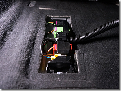
This is the "Connector Station" under the genuine power seat.
![Image]()
According to the service manual, there are four connectors (couplers).
They are "10-pin connector (black)", "6-pin connector (green)", "10-pin connector (red)", and "3-pin connector (yellow)".
![Image]()
And there is a "2-pin connector (black)" in the middle of the wiring of the seat belt anchor buckle. (See below)
![Image]()
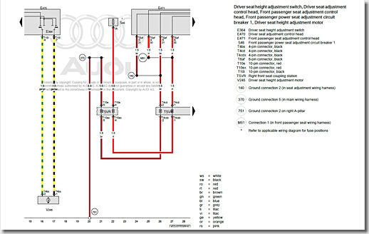
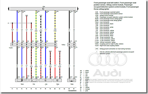
This is the wiring diagram of the "Front Seat Coupling Station".
You can see that the power supply (red) and the ground (brown) are connected to the "10-pin connector (red)". The power source for the electric power seat.
![Image]()
Continuation of the wiring diagram.
You can see that signal 1 (black), signal 2 (blue), and ground (brown) are connected to the "3-pin connector (yellow)". Signals for the "Side Airbag Igniter".
And you can see that signal 1 (brown/black) and signal 2 (green/yellow) are connected to "10-pin connector (black)". Signals for the "Seat Belt Latch Sensor".
When the anchor tongue is inserted into the anchor buckle of the seat belt, signal 1 and signal 2 are short-circuited. It indicates that the seat belt is latched.
![Image]()
Continuation of the wiring diagram.
You can see that the seat heater power (black/yellow) and ground (brown) are connected to the "6-pin connector (green)".
And you can see that signal 1 (black/white) and signal 2 (brown/black) of the temperature sensor are connected to the "6-pin connector (green)".
![Image]()
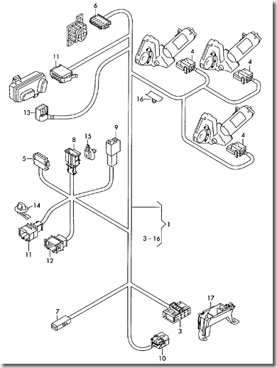
This is the block diagram of "Seat Frame Wiring Harness".
I found the part code of the connector housing from this figure.
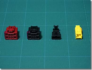
![Image]()
I imported the connector housings from Germany.
From the left, "4F0 937 733 B" (red), "4F0 937 733" (black), "3B0 972 712" (black), and "8J0 972 576" (yellow).
![Image]()
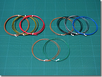
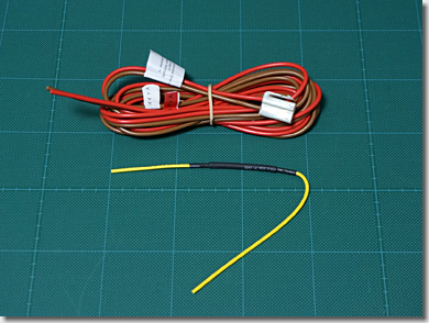
In order to bring the special wire harness close to the same quality as automobile manufacturers, I prepared thin-walled low-voltage electric wires for automobiles.
They come in a variety of color combinations and thicknesses, depending on the application.
![Image]()
These are the power cable and the "Side Airbag Canceller", attached to the RECARO seat package.
I do not use these cables.
![Image]()
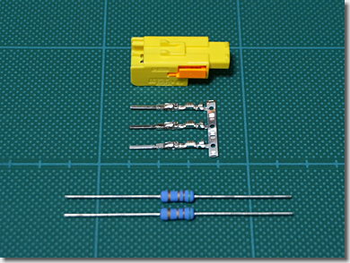
First, made the original "Side Airbag Canceller".
The 3-pin connector housing (yellow) is "8J0 972 576" and the contact pins are "000 979 035 E".
The two resistors are 5.1Ω (2W).
![Image]()
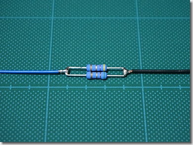
By connecting these in parallel, the resistance value will be approximately 2.5Ω (4W).
![Image]()
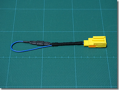
Crimp contact pins on both ends and protect the resistor with "Heat Shrink Tube".
Then wrap tesa "Fleece Adhesive Tape" for automobile.
![Image]()
Next, make the original "Power Cable".
The 10-pin connector housing (red) is "4F0 937 733 B" for the vehicle side of the electric power seat and the 2-pin connector housing (white) is "T type 2 poles" for the RECARO seat side.
![Image]()
Crimp, protect and wrap them.
![Image]()
And, make the original "Seat Belt Latch Sensor Cable".
The 10-pin connector housing (black) is "4F0 937 733" for the vehicle side of the seat belt sensor and the 2-pin connector housing is "3B0 972 712" for the seat side of the seat belt sensor.
![Image]()
Crimp, protect and wrap them.
![Image]()
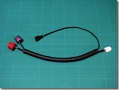
Put the two wire harnesses together and protect them with the "Gel Coat Tube" of φ13mm.
It looks like a genuine wire harness.
Now you are ready to install the RECARO seat with the special wire harness that it possible to "Coupler-On".
I replaced the genuine electric power seat with a RECARO seat.
Without damaging the original wire harness from the body side, I analyzed the electronic circuit diagram in the service manual, and made a special wire harness that it possible to "Coupler-On".
I hope this information will be helpful for your enjoying DIY.
This is the "Connector Station" under the genuine power seat.
According to the service manual, there are four connectors (couplers).
They are "10-pin connector (black)", "6-pin connector (green)", "10-pin connector (red)", and "3-pin connector (yellow)".
And there is a "2-pin connector (black)" in the middle of the wiring of the seat belt anchor buckle. (See below)
This is the wiring diagram of the "Front Seat Coupling Station".
You can see that the power supply (red) and the ground (brown) are connected to the "10-pin connector (red)". The power source for the electric power seat.
Continuation of the wiring diagram.
You can see that signal 1 (black), signal 2 (blue), and ground (brown) are connected to the "3-pin connector (yellow)". Signals for the "Side Airbag Igniter".
And you can see that signal 1 (brown/black) and signal 2 (green/yellow) are connected to "10-pin connector (black)". Signals for the "Seat Belt Latch Sensor".
When the anchor tongue is inserted into the anchor buckle of the seat belt, signal 1 and signal 2 are short-circuited. It indicates that the seat belt is latched.

Continuation of the wiring diagram.
You can see that the seat heater power (black/yellow) and ground (brown) are connected to the "6-pin connector (green)".
And you can see that signal 1 (black/white) and signal 2 (brown/black) of the temperature sensor are connected to the "6-pin connector (green)".
This is the block diagram of "Seat Frame Wiring Harness".
I found the part code of the connector housing from this figure.
I imported the connector housings from Germany.
From the left, "4F0 937 733 B" (red), "4F0 937 733" (black), "3B0 972 712" (black), and "8J0 972 576" (yellow).
In order to bring the special wire harness close to the same quality as automobile manufacturers, I prepared thin-walled low-voltage electric wires for automobiles.
They come in a variety of color combinations and thicknesses, depending on the application.
These are the power cable and the "Side Airbag Canceller", attached to the RECARO seat package.
I do not use these cables.
First, made the original "Side Airbag Canceller".
The 3-pin connector housing (yellow) is "8J0 972 576" and the contact pins are "000 979 035 E".
The two resistors are 5.1Ω (2W).
By connecting these in parallel, the resistance value will be approximately 2.5Ω (4W).
Crimp contact pins on both ends and protect the resistor with "Heat Shrink Tube".
Then wrap tesa "Fleece Adhesive Tape" for automobile.
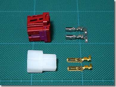
Next, make the original "Power Cable".
The 10-pin connector housing (red) is "4F0 937 733 B" for the vehicle side of the electric power seat and the 2-pin connector housing (white) is "T type 2 poles" for the RECARO seat side.
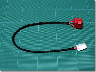
Crimp, protect and wrap them.
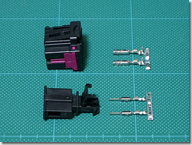
And, make the original "Seat Belt Latch Sensor Cable".
The 10-pin connector housing (black) is "4F0 937 733" for the vehicle side of the seat belt sensor and the 2-pin connector housing is "3B0 972 712" for the seat side of the seat belt sensor.
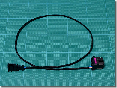
Crimp, protect and wrap them.
Put the two wire harnesses together and protect them with the "Gel Coat Tube" of φ13mm.
It looks like a genuine wire harness.
Now you are ready to install the RECARO seat with the special wire harness that it possible to "Coupler-On".


